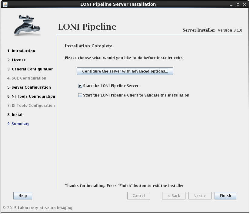
- Editing Preferences.xml
- Server Configuration Tool
- General
- Hostname and port
- Temporary directory
- Scratch directory
- Log file location
- Use privilege escalation and Enable guests
- Persistence
- Days to persist session status
- History directory
- Crawler persistence URL
- Server library
- Grid
- Grid engine native specification
- Job name prefix
- Grid complex resource attributes
- Grid Variables Policy
- Max number of parallel submission threads
- Max number of resubmissions for “error stated” jobs
- Grid total slots
- Array jobs
- Grid plugin
- Finished job retrieval method
- Pipeline user is a grid engine admin
- Grid job accounting
- Access
- Server admins
- Directory access control
- User management
- Non-user-based Job management
- Workflow management
- Mappings
- Packages
- Executables
- Utilities
- Advanced
- Failover
- Log email
- Network
- Maximum number of threads for active jobs
- HTTP query server
- Automatically clean up old files
- Maximum number of metadata threads
- Warn when free disk space is low
- Server status
- Directory source recursive timeout
- External network access queue
- Validation warning
- NFS directories for validation
- Check and verify output files
- Test server library
You can customize your Pipeline server in two ways. Either by editing preferences.xml file, or using the Server Configuration Tool.
3.1 Editing Preferences.xml
You can find out the XML tags for a particular preference, or read the old version of server guide, here: Server Preferences Configuration.
This tool is included in the Pipeline distribution and can be opened by typing:
$ java -classpath Pipeline.jar server.config.Main
The Server Configuration Tool will open with default values. If you already have a Pipeline server preferences file, you can load it up by pressing the Load button on lower right.
You can view and make changes in any of the fields (to be explained in details below). After you are done, just click Save button on lower right corner. It will first validate your inputs and then save it to a file. If you already have a preferences file loaded, it will be overwritten, otherwise, it will ask where you want to save this newly created preferences file. At any time, you can restore to default values by clicking Restore button on lower right corner. After restore, all the changes after the last save will be discarded.
When you are done configuring preferences, you can start the Pipeline server with saved preferences file by
$ java -classpath Pipeline.jar server.Main -preferences preferences.xml
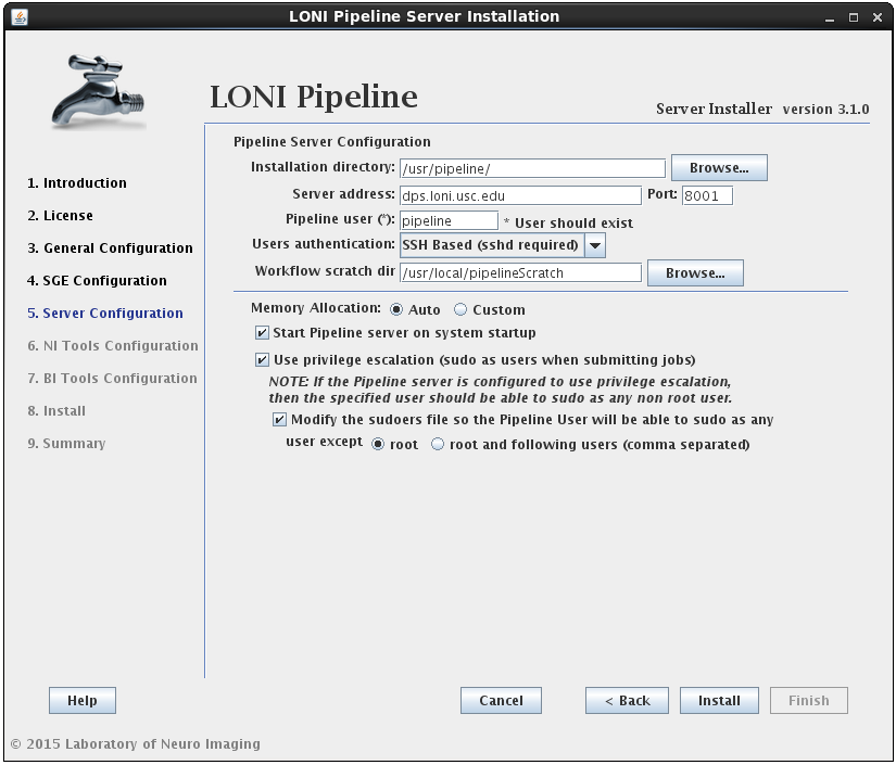
3.2.2.1 General

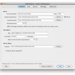
The General tab lets you specify the most basic information needed for the Pipeline server.
3.2.1.1 Hostname and port
The server hostname is the hostname of the computer that you want the server to run on. It requires the fully qualified domain name of the computer that it is on.
The default port number is 8001. If you are using default port, you can leave the field blank. You can identify the server by just using the server hostname. If you use a non-default port, you have to identify the server by hostname:port format.
3.2.1.2 Temporary directory
The temporary directory is where all intermediate files for all the executed programs are stored on the server. This directory should be accessible from the Pipeline server as well as compute nodes. The Pipeline server will create a structure under there, and the compute nodes will read from and write to that directory. For example if you specify /ifs/tmp, the Pipeline server will create a directory /ifs/tmp/username/timestamp and put all the working files there.
Where username is the user that is running the server and timestamp is the time at which each workflow gets translated before execution. Inside each of those ‘timestamp’ folders will be all the intermediate files produced by executables from submitted workflows. Depending on the number of users using your server and the kind of work they do, this directory can balloon up very quickly.
If you check the Secure checkbox, the Pipeline server will store the temporary directory more securely. Each workflow’s directory will be accessible only for the user who started the workflow.
It is suggested to specify a non-existing directory as temporary directory if you start your Pipeline server for the first time. The Pipeline server will create appropriate files at start up.
3.2.1.3 Scratch directory
The scratch directory is utilized in workflows to make data sink paths portable across Pipeline environments. In particular, this field is linked to the {$tempdir} special variable available to all Pipeline workflows. The server administrator should configure this to be the path to a directory to which all Pipeline users can write. If the grid is utilizing NFS, this directory must be available to all the compute nodes that the Pipeline server manages. When configured, this value is stored in the Pipeline user’s home directory, inside the userdata.xml file. Upon connecting to the Pipeline server, the client requests this value and stores it in the local userdata.xml file. Any references to the {$tempdir} variable in workflows are replaced with the configured value.
3.2.1.4 Log file location
If you want to explicitly set the directory location that your log files will write to, you can specify the path here. In order to define the prefix in which the log files will be named, simply add that to the end of the directory path. The unique number denoting the log file will be appended onto the file name. For example, if we specify log file location as /nethome/users/pipelnv4/server/events.log, then log files will be created in the /nethome/users/pipelnv4/server/ directory, and will be named events.log.0, events.log.1, and so forth.
Note : The directory of log files MUST EXIST, before starting the server.
3.2.1.5 Use privilege escalation
When you have different users connecting to your Pipeline server, you might want to enforce different access restrictions on each user. If you’re running your Pipeline server on a Linux/Unix based system (including OS X), you can enable privilege escalation which will make the Pipeline server issue commands as the user who submits a workflow for execution. For example, if user ‘jdoe’ connects to a Pipeline server with privilege escalation enabled, any command that is issued on behalf of that user will be prefixed with ‘sudo -u jdoe ‘. This way all the files that are accessed and written by the user on the Pipeline server will be done on behalf of ‘jdoe’.
Remember, there is no harm in not enabling privilege escalation on your Pipeline server. All files will simply be created and read as the Pipeline server user. You will be giving uniform access to your system to all users. Additionally, it makes it easy to lock down the access of all Pipeline users because you only have to lock down the access of one actual user on your system; the Pipeline user.
In order to enable this feature in the Pipeline, you need to do two things. 1) modify your system’s sudoers file to allow the user that runs the Pipeline server to sudo as any user that will be allowed to connect to the system and 2) check “Use privilege escalation” under server configuration tool.
Enable guests option lets you grant guest log in to the server. The guest username is randomly generated by the client with the format “guest-[random 8-character string]”. If enabled, the guest will be able to connect to the server, submit workflow as Mapped guest user, and retrieve workflows by this guest. Regular users will not be affected in any way, and each guest will not have access to other guests’ workflow either. Pipeline Web Start and Workflow Library Navigator are set up with guests enabled.
3.2.1.6 Persistence
Pipeline server uses hsqldb to store information, including workflow status and module status. By default, it is stored in Pipeline server’s memory, and will be removed when the Pipeline server stops. Alternatively, you can start a hsqldb server and make it save to an external file. You can go to hsqldb website to download the jar file. To start a hsqldb process, run something like this:
java -cp ./lib/hsqldb.jar org.hsqldb.Server -database.0 file:/user/foo/mydb -dbname.0 xdb
After successfully starting hsqldb, you can put the persistence database information to server’s preference. The URL for the above example will be:
jdbc:hsqldb:hsql://localhost/xdb
Username and password can be configured as well, refer to hsqldb documentation for more information.
3.2.1.7 Days to persist status
This item specifies number of days a completed workflow can be stored on the server. The Pipeline server periodically checks and cleans up completed workflow sessions older than the number of days specified (counting from the workflow session’s completion time). The default value is 30 days. If a session is cleared, all its temporary files under the temporary directory will be removed.
3.2.1.8 History directory
History directory is a directory to store history/logging information on the server. If specified, each submitted workflow will be stored with timestamps and user information, even when user resets the workflow or the workflow is automatically removed from active sessions. Pipeline admins could see the history lists under server terminal’s Workflows tab and Users tab (check Show full history).
3.2.1.9 Crawler persistence URL
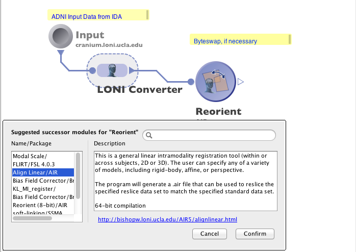
This item specifies the hsqldb URL of optional workflow crawler. If a valid hsqldb URL is specified, Pipeline server will start a workflow crawler thread, which crawls every submitted workflows (and history workflows if there exists) for module usage statistics. The statistical information is used to help user select and explore modules. Features such as Module Suggest, ranked server library search result, and Workflow Miner all use statistics gathered from crawler.
The crawler persistence database uses hsqldb, like the main persistence database. Setting it up is similar to setting up main persistence, with slight changes in db name and ports, for example
Main: java -cp ./lib/hsqldb.jar org.hsqldb.Server -database.0 file:/user/foo/maindb -dbname.0 xdb -port 9002
Crawler: java -cp ./lib/hsqldb.jar org.hsqldb.Server -database.1 file:/user/foo/crawlerdb -dbname.1 cdb -port 9003
URLs
Main: jdbc:hsqldb:hsql://localhost:9002/xdb
Crawler: jdbc:hsqldb:hsql://localhost:9003/cdb
3.2.1.7 Server library
When Pipeline client users connect to a server, the client syncs up the library of module definitions available on that server. The location of that library on the server is specified by Server library location field in the preferences. By default, the location is set to one of the following locations (based on OS), so you don’t need to specify this preference if you’re happy with it:
- Linux/Unix – $HOME/documents/Pipeline/ServerLib/
- OS X – $HOME/Documents/Pipeline/ServerLib/
- Windows – %HOME%\Application Data\LONI\pipeline\ServerLib\
- Windows Vista/Seven – %HOME%\Documents\Pipeline\ServerLib\
Put all the module definitions that you want to make available to users into the directory, when the server starts up, it reads in all the .pipe files in the directory (and all its sub directories). When clients connect, they will obtain a copy of the library on their local system. The server monitors the directory for changes/additions in any of the files while it runs. if change occurs, the server will automatically checks the files (no restart required) and synchronize clients again when they reconnect. Even when clients are connected during the change, they will get the new version of the server library instantly.
By default, the sever monitors the timestamp of the server library directory. However, if you have sub directories and you make changes inside these sub directories, server will not see the change as the library directory’s timestamp was not changed. You can solve this by checking “Monitor library update file”, and specifying a path (by default, it’s a file called .monitorFile under your library directory), this way the Pipeline server will monitor this particular file, instead of the library directory, to know when the library is updated. So when you update your server library, you can update this file to inform the server the library has been updated.
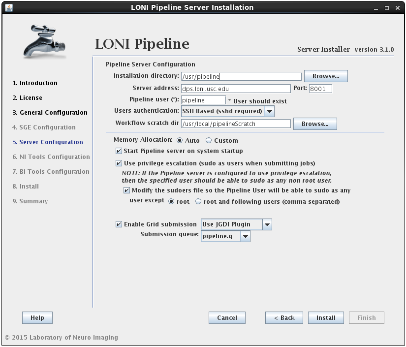
3.2.2 Grid

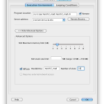
The Grid tab lets you specify the grid-related parameters for the Pipeline server. If it’s not enabled, all jobs will run locally on the Pipeline server machine.
3.2.2.1 Grid engine native specification
This field lets you specify a native specification string that goes along with your job submission (if none of that makes any sense, just skip this preference because you don’t need to use it on your server). On the LONI Pipeline server we use the following native specification preference:
-shell y -S /bin/csh -w n -q pipeline.q -b y _pmem _pstack _pcomplex _pmpi -N _pjob
The native spec you should use for your installation will vary, but if you’re using an Oracle Grid Engine (previously known as Sun Grid Engine) installation and you want to use the same string, you’ll want to change the -q pipeline.q to reflect the submission queue (if any) that you will be using.
Optionally, you can add _pmem and _pstack to the native specification. _pmem enables user define maximum memory per module, and _pstack enables user to define the stack size. Both of these can be configured by the user using the latest Pipeline client, and they all use the default set by the grid engine unless user specifies.
You can also add following:
_pcomplex which refers to Grid complex resource attributes.
_gridvars which refers to Grid Variable Policy ( Available since version 5.3)
3.2.2.2 Job name prefix
In some environments, server admins may want to visually see which jobs are submitted by pipeline and which jobs are not. This can be done by setting prefixes for all jobs which are started by pipeline. The “Job name prefix” field expects a string value which will be prepended on each job’s name. For example, you could set the value of it to “pipeline_” and all job names will start with it ( i.e. pipeline_echo, pipeline_sleep, pipeline_bet, pipeline_reallign, etc. ).
IMPORTANT: This change will be in effect ONLY if Grid Engine Native Specification contains the _pjob value. The “_pjob” value sets the name of each job with the same name as executable filename. If _pjob is not specified, then prefix won’t be prepended to job’s name.
3.2.2.3 Grid complex resource attributes
Grid complex resource attributes lets the Pipeline server check for the jobs which are submitted by Pipeline but not monitored by it anymore. This happens when the job is in a submission process and the server turns off. When the job submission is complete and Pipeline is down, the job id will not be written in the Pipeline database. Which means that this job will use the slot, but Pipeline will not “remember” the job id. When server restarts it gets the list of running jobs on cluster and compares with its database. To determine which jobs are submitted with current server Pipeline uses grid complex resource attributes. When Pipeline finds jobs which are submitted by current Pipeline but are out of control, it deletes them to free up the slot.
This tag allows you to assign custom complex attributes to all submitted jobs by the server, which will make jobs identifiable. You can have multiple values in the tag seperated by comma. For example
pipeline, serverId=server1
Following defines two attributes 1) pipeline which is equal to TRUE and 2) serverId which is equal to server1.
This tag is just a definition of complex attributes. In order to use them you have to define _pcomplex in Grid engine native specification. In our case, the _pcomplex will be replaced with -l pipeline -l serverId=server1 when submitting the job to the grid.
Note that the Grid manager has to be configured properly to accept jobs with given resource attributes.
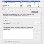
3.2.2.4 Grid Variables Policy
Starting from Pipeline version 5.3, server administrators are able to control grid engine variable usage and set restrictions to them and their values.
By default, if nothing is set, Pipeline will not allow any grid variables to be used by users.
To configure Grid Variable Policy, open the Configuration tool’s Grid Panel and follow the example instructions below:
Let’s say we want to give users a permission to use variables h_vmem and h_stack. So we need to select “Disallow all variables, except specified” from drop down box Grid Variables policy and write in the textbox semicolon separated values:
h_vmem; h_stack
As each grid engine is different, there can be different formats of how to specify grid variables. For example for SGE we need to have “-l” prefix before each resource value. So we need to put “-l” in “Prefix before each tab” field.
Any of these variables may require a suffix to be attached after their values, for example in SGE h_vmem needs to be written in following format h_vmem=5GAs you can see there is a G suffix and we need to have that in our policy.
To introduce the suffix, we will change the “Grid Variables policy” to:
h_vmem [G]; h_stack[m]
Where “G” is the suffix for h_vmem variable and “m” is suffix for h_stack. After saving this change, without any server restart, Pipeline will not allow any grid variable to be used other than these two.
Alternatively Pipeline administrations can set limits for values, for example if we want h_vmem to have value from 1Gb to 8Gb and h_stack from 0mb to 256mb, then we’ll need to have following configuration:
h_vmem [1-8G]; h_stack [0-256m]
If you want to specify some specific values, but not ranges of numbers, then you have to use following syntax:
h_specific_value ( valueX, valueY, valueZ )
If you combine this with previous configs, then you’ll get:
h_vmem [1-8G]; h_stack [0-256m]; h_specific_value ( valueX, valueY, valueZ )
So as you can see, ranges must be specified with following format [Min-Max Suffix] and specific values must be ( Comma, Separated, Values )
Another option is to allow everything except some of the variables, this has the same format and in order to use it, select “Allow all variables, except specified” item from drop down box.
And finally, you can set multiple ranges for each variable. This becomes useful when you want to give a choice of suffixes to users. For example if you want your users be able specify the h_vmem and in Gigabytes and in Megabytes. So the configuration should look like this:
h_vmem [1-8G, 1000-8000M]; h_stack [0-256m]; h_specific_value ( valueX, valueY, valueZ )
If the user doesn’t specify a suffix to value ( for example : 4 instead of 4G ) then Pipeline will automatically use configured suffix. If there are multiple suffixes, Pipeline will set the first suffix as default.
NOTE: The Grid Variable Policy will be enabled only when there is _pgridvars variable defined in Grid Engine Native Specification field. Otherwise, the Pipeline validation will only validate grid variables, but will not include them in job submission specification. Here is an example of native specification which will enable the Grid Variable Policy:
-shell y -S /bin/csh -w n -q pipeline.q -b y _pgridvars _pcomplex _pmpi -N _pjob
So if you want to use Grid Variable Policy, make sure you have _pgridvars variable defined in native specification.
Please see Grid engine native specification for more details.
3.2.2.5 Grid maximum submit threads
This field lets you specify the number of parallel job submissions. For example, if you specify 1, it will submit jobs one by one. If you specify 10, it will allow maximum of 10 parallel submissions at a time.
3.2.2.6 Grid total slots
The Pipeline client lets user to see the activity of the Pipeline server, how busy the server is and how many total slots are available on the grid. These total slots fields tell the server how many total slots available on the grid either dynamically (by running the command) or statically (by providing a number).
Grid total slots command asks for a command line query to get the total number of available slots for the queue that the Pipeline server is using. Refer to your cluster management documentation for the appropriate query. By using this tag, the server will query the grid engine periodically to get the latest number of available slots, and update the number automatically, and broadcast the new number to clients.
The grid total slots field lets you give the number of total grid slots for the cluster. This number is less accurate if the slot counts on the grid changes regularly.
You can provide both dynamic command and a static number, server will use the dynamic command first, and if it doesn’t work, it will use the static number.
3.2.2.7 Max number of resubmissions for “error stated” jobs
When submitting jobs to the grid, jobs can fail before starting to run. For example, if the job submitted with sudo but the node where the execution started doesn’t have information about that user, then the grid engine would complain and put the job in error state. In this case, it is possible that resubmission of this job would put the execution in another node which doesn’t have the same problem.
This property tells pipeline how many times to resubmit the job after its state is set to “error”. Please note that this doesn’t mean that every execution which fails pipeline will try to resubmit, no, it will not resubmit any job which execution successfully started but the exit code of the executable is other than 0. For example, if you run cp command with one argument, it will fail, but pipeline won’t resubmit it because the execution has been successfully completed independent of its result.
3.2.2.8 Array jobs
Sometimes job submission can take a long time when each instance of a module is submitted as an individual job. Array jobs solve this problem and dramatically improve the job submission speed. Starting from version 5.1 you can enable array jobs on the Pipeline server so instead of submitting individual jobs it can submit array of jobs. This feature improves the speed of submission especially for modules with multiple hundreds/thousands of instances. Dependent of the module’s number of instances there is 10%-65% speed improvement when using array jobs versus individual jobs.
Parameters
When a workflow is started and it contains a module with large number of instances, submitting array jobs small number of tasks at the beginning will be time efficient.
Before submitting the job array, Pipeline has to create a special script and configure it for each instance. This procedure takes time and during the preparation grid engine will be idle. For example: Let’s say we have a module with 1000 instances. It will take shorter time to prepare 50 jobs for submission than 1000 jobs. So you can configure the value of “break into chunks when number of jobs exceeds“, which tells Pipeline to split into chunks instances of those modules which has cardinality X and more. It is a positive integer number and indicates the minimum cardinality value the module is required to have in order to split into chunks.
The chunk size tells the Pipeline server the size of an array job. So if we set break into chunks when number of jobs exceeds 200, and chunk size 50, and user submits a workflow with 200 instances, the Pipeline server will divide them into 4 array jobs, each with 50 instances.
Sometimes after the first chunk it is better to gradually increase chunk size, because after the first chunk submission the grid engine will not be idle and we can afford submitting larger array jobs. If this is enabled, after the first submission the Pipeline server will double the chunk size upon each iteration.
For example: If we have a module with 1000 instances and chunk size is 50, break into chunks when number of jobs exceeds 200, then it will submit array jobs with following sizes
| Array Job # |
Number of instances |
Total submitted so far |
| 1 |
50 |
50 |
| 2 |
100 |
150 |
| 3 |
200 |
350 |
| 4 |
400 |
750 |
| 5 |
250 |
1000 |
The maximum chunk size sets the upper limit of the increase. The Pipeline server will double the chunk size for each array job until the maximum chunk size is reached.
There is one special case: during the submission Pipeline checks how many instances remain to be submitted and when the remaining is more than the limit but there is only less than 10% left, then remaining instances will be carried with last job array. Here’s is an example with total of 768 instances.
| Array Job # |
Number of instances |
Total submitted so far/ Remaining |
| 1 |
50 |
50 / 718 |
| 2 |
100 |
150 / 618 |
| 3 |
200 |
350 / 418 |
| 4 |
418 |
768 / 0 |
The last 418 is more than the specified 400. But 418-400=18 which is less than 76 ( 10% of total 768 instances).
3.2.2.9 Grid plugin
The Pipeline server lets you create your own plugins to communicate with various Grid managers (see also Pipeline Grid Plugin API Developers Guide). Pipeline package contains two built-in plugins for Oracle Grid Engine (previously known as Sun Grid Engine) which are JGDIPlugin and DRMAAPlugin. In installed package of Pipeline, under the lib directory there is directory called plugins in which you can find these two plugins.
If you are using either JGDI or DRMAA, just select it under the drop down, everything will be filled in for you. If you are using your customized plugin, you need to specify the jar file location, and class name of the Plugin used by Pipeline.
IMPORTANT: Some plugins require to be defined in class path. For example DRMAA Plugin requires from you to put the path of drmaa.jar in class path when starting the server. So to start the server with DRMAA plugin you need to have
$ java -cp .:/usr/pipeline/dist/lib/plugins/drmaa.jar

Pipeline.jar server.Main
3.2.2.10 Finished job retrieval method
This option is mostly for advanced cases. When Pipeline server restarts,it is possible that some of the jobs which continue to run will finish while the server is offline. In this case when server starts up in needs to get information about the finished job from grid engine’s accounting database or files or some other place. Different grid plugins have different options for retrieving information about finished jobs. For example, the JGDI Plugin supports the option for retrieving information from SGE’s ARCo database. It may be possible that the same plugin has different methods to get that information and in that case Pipeline server administrator would want to choose the method.
This property requires a string value which will be sent to the grid plugin. Most of the grid plugins have their default methods for retrieving job information. In those cases this property is not needed to be set. For example, if we want to use ARCo database from JGDI plugin we could just leave this property empty ( as ARCo database is the default method for JGDI plugin ) or just simply set it to “arco”. Please refer to grid plugin documentation to get more information about what methods they support and how to configure them.
3.2.2.11 Pipeline user is a grid engine admin
When privilege escalation is set to true, pipeline submits jobs on behalf of the users who submit the workflow. If Pipeline user is a Grid Engine admin ( configured by grid engine administrators ) and if it is able to delete any users jobs, then this property is recommended to be unchecked as the performance will be faster.
When this checkbox is selected, then pipeline will tell the grid plugin to kill the job on behalf of the user. For example in SGE that call would be sudo -u #user qdel #jobId*, where #user is the username and #jobId is job’s Id.
3.2.2.12 Grid job accounting
After Pipeline server restarts some jobs may already been finished or changed their status. This events haven’t been caught as Pipeline server was not running at that moment. In order to get the status of “missed” events, Pipeline gets information from configured Sun’s Accounting and Reporting Console (ARCo) database. Note this feature is only tested for Oracle Grid Engine (previously known as Sun Grid Engine) with JGDI and DRMAA plugins, if you are using another grid manager, and it does not work, please report it on our Pipeline forum.
Assuming ARCo database is configured and running (refer to ARCo website and your system administrator for help). To configure ARCo database in Pipeline you need to put information about the database URL, username, and password. The URL looks like this:
jdbc:mysql://hostname/db_name
3.2.3 Access

The Access tab lets you configure user-access and workflow management for the Pipeline server.
3.2.3.2.1 Server admins
This field lets you specify a list of user names that are Pipeline server admins. Pipeline server admins can connect to the server via Pipeline Server Terminal Utility to monitor and manage the server. They can view, stop, delete anyone’s workflows on the server, view a list of connected users and their IP addresses, server’s memory and thread usage, as well as edit all the server preferences discussed on this section.
If there’s no server admin specified yet, you need to directly edit server’s preferences.xml file. The xml element is called ServerAdmins. For example, if you want john and jane to be server admin, then preferences.xml file should look like this:
<preferences>

...(other items)...

<ServerAdmins>john, jane</ServerAdmins>

</preferences>
After saving changes to preferences.xml file, you need to restart Pipeline server.
3.2.3.2.2 Directory access control
The Pipeline server lets you control user access on the executables/modules they can run and files they can browse on the server. Below is a matrix chart for different mode:
| Mode |
Executables Access Control |
Remote File Browser Access Control |
| 0 |
Never |
Never |
| 1 |
No with exceptions |
Never |
| 2 |
Yes with exceptions |
Never |
| 3 |
No with exceptions |
No with exceptions |
| 4 |
Yes with exceptions |
Yes with exceptions |
| 5 |
No with exceptions |
Same as shell permissions |
| 6 |
Yes with exception |
Same as shell permissions |
| 7 |
Same as shell permissions |
Same as shell permissions |
| 8 |
Users with shell access: Same as shell permissionsUsers without shell access: Yes with exceptions |
Users with shell access: Same as shell permissionsUsers without shell access: Yes with exceptions |
Never means Pipeline server will not do any access control restrictions for any user. Note this will not affect operating system’s authentication and access control, in other words, the credentials required to connect to the Pipeline server and the rights required to execute programs will not be affected by the settings here. No with exceptions means access control is not enabled for all users except those marked in controlled users will be restricted. Yes with exceptions means all users will be restricted except for those specified in controlled users will be allowed. Same as shell permissions means the remote file browser will act as if user logged in to the server using shell.
Controlled users
This is a list of users separated by commas (i.e. john,bob,mike) which will indicate conditional users. Depending on the control mode, These users will be restricted or allowed.
Controlled directories
This is a list of directories separated by commas (i.e. /usr/local,/usr/bin), which will be the only directories allowed for restricted users.
Examples
We want to restrict user john, bob, mike to execute programs only in: /usr/local and /usr/bin, and let every user browse using remote file browser as shell does, we would have these configurations:
Mode: 5
Controlled users: john,bob,mike
Controlled directories: /usr/local,/usr/bin
Another example, if we want to restrict all users to execute programs only in: /usr/local and /usr/bin, but allow users john, bob, mike to run without restrictions, and let every user browse using remote file browser as shell does, we would have these configurations:
Mode: 6
Controlled users: john,bob,mike
Controlled directories: /usr/local,/usr/bin
3.2.3.2.3 User management
Pipeline version 5.1 introduces new user management feature. It has a special algorithm that provides a fair share resource to all users.
How it works
When enabled, you need to set up a percentage that will limit each user’s jobs. The percentage is calculated by taking the number of free slots at submission time.
For example: the Pipeline server has 150 slots available and the user management percentage is set to 50%.
The first user will be able to use 50% of 150, so 75 slots will be used by user A.
Then User B will be able to submit 50% of free slots which is 50% of (total 150) – (user A’s 75) = 50% of (free 75) = 37 and so on.
Pipeline server constantly checks and monitors the user usage and adjusts each user’s limit.
3.2.3.2.4 Non-user-based Job management
Pipeline version 7.0 introduces new job management feature that has limits independent of the limits on the user who submitted it. The job management algorithm has been updated to consider both user management and job management factors when decided to run a job.
How it works
<EnableNodeManagement>true</EnableNodeManagement>
<ControlledNodes>
<node name=”ControlledModule1″ limit=”200″ />
<node name=”ControlledModule2″ limit=”150″ />
</ControlledNodes>
When enabled, you need to set the module name and limit for number of jobs that can be run by a module with this name. The limit is global across all users and jobs submit via Pipeline.
For example: A user runs a module named ControlledModule1 which submits 180 jobs. Other users who run modules with this same name (name only, the actual definition of the module is not considered) will find that this module can only submit 20 jobs and the rest will get backlogged. This assumes that their user quota (see above) has not been reached yet. If they user quota is already reached, Pipeline will not submit any jobs.
This feature is useful for jobs that have special limitations that need to be enforced. For example, a job that communicates with some external service and you don’t want to overload this service with thousands of requests. You can create a uniquely named module to describe this job and limit it across the server to protect resources.
3.2.3.2.5 Workflow management
Workflow management lets you manage active (running and paused) workflows per user on the Pipeline server. If it’s enabled and a limit has been set, the number of active workflows for any single user will not exceed the limit. Any workflow submitted after the limit is reached will have a backlogged status. They will be queued until any of the user’s running workflows completes.
3.2.4 Mappings
Updated: The Packages and Executables tabs are now disabled when running configuration tool. Instead, you can edit by connecting to the running Pipeline server using Server Terminal > Preferences tab. All the values under Packages and Executables tabs will be dynamically updated without restarting the server.
The Packages and Executables tabs give the administrator the ability to configure mappings that allow for Pipeline workflow portability between Pipeline servers. In particular, information about an executable (in the form of the executable package, version, or name) can be used to determine where that executable resides on a given file system and whether it requires the setting of certain environment variables. The following sections describe this interface in greater detail.
3.2.4.1 Packages

The Packages tab allows you to set up a list of available packages/tools and their locations on the server. This allows the Pipeline server automatically correct user-submitted module’s executable location based on its package name and version.
There are five columns in the table, package name and version, location, variables and sources. Package name and version are used to compare against user-submitted module definition, they should uniquely identify a package on the server. Version value can be empty which corresponds to empty version in the module’s definition. Package location is the local path to the package where all the executables are located. Variables and sources are optional, which defines environmental variables needed for the package (in name=value format) and scripts to be sourced before running respectively.
To add a package, click on Add and put name and version of the package. You can double-click on any of the columns to edit them, for Variables and Sources, you’ll see a new dialog pops up after the double-click, to let you easily input multiple entries. To delete a package, just select it and click Remove. Make sure to hit the ‘Save Server Preferences’ button to save the settings.
3.2.4.2 Executables

The Executables tab improves the portability of Pipeline modules in the following sense. If we have a Pipeline module that runs /usr/bin/java -jar /usr/local/some_package-1.0/bin/program.jar, we can use the package mapping utility (described above), to say that program.jar belongs to the package ‘some_package’, version ‘1.0’, include this information in both the Pipeline module definition and the Packages tab in the server terminal GUI, and we would be able to share this module with a user connecting to a different Pipeline server (with the proper configuration). However, we are still assuming that both systems have /usr/bin/java. With the executables mapping, the executable name ‘java’ can be configured to map to any location, making the module fully portable.
Much like the Packages tab, the Executables tab allows the administrator to create a correspondence between executables and their location in the relevant filesystem. In this case, the interface has three columns. In the first column, the user needs to specify the executable name (e.g., java, perl). The second column requires the user to specify a version number for the executable. This can be useful if Pipeline users are utilizing several different versions of an executable and need to be able to specify the version needed by a particular Pipeline module. If the version number is not relevant, an asterisk (*) can be used to indicate any version. Finally, the last column, labeled ‘Location,’ is used to indicate the path on the grid’s execution hosts where the executable resides (e.g., /usr/bin/java).
To add an executable, click on Add and enter the executable filename, version, and full path. To delete an executable, just select it and click Remove. Again, make sure to hit the ‘Save Server Preferences’ button to save the settings.
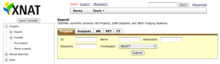
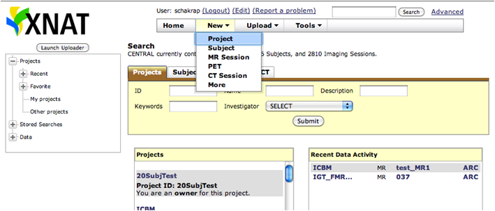
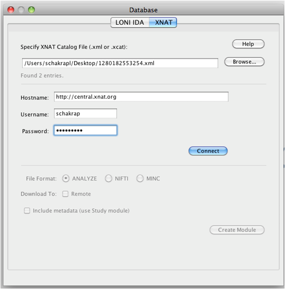
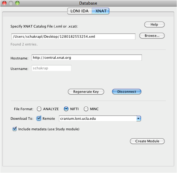
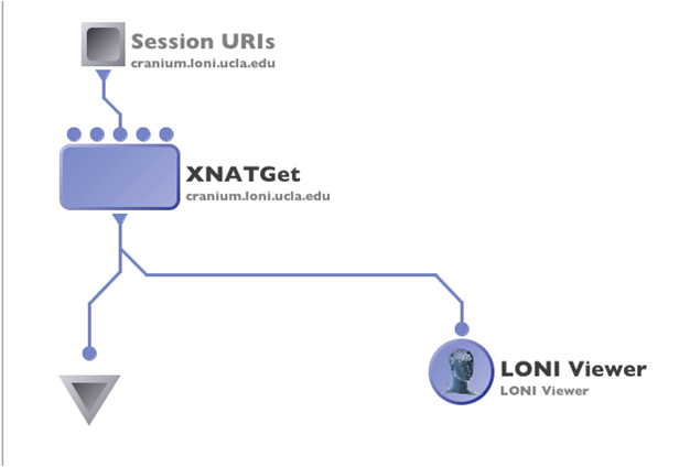
3.2.4.3 Utilities
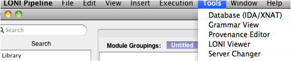
The Pipeline makes use of several utility plugins and the amount of these plugins will undoubtedly increase as the Pipeline grows. Currently, the three independent applications that the Pipeline uses are Smartline, XNAT, and IDA. These java applications are completely portable; they are packaged as jar files and are included in the standard Pipeline distribution. When setting up a Pipeline server, the administrator needs to perform three steps to ensure that these tools can be used by Pipeline clients which connect to it. First of all, the xnat, smartline, and idaget directories need to be moved to a common location. Secondly, this directory needs to be configured into the Package Mapping for the server. In particular, the package name “Pipeline Utilities” with the generic version “*” should map to /path/to/utilities, where /path/to/utilities is a directory containing the xnat, smartline, and idaget directories. This can be done very easily under the Preferences->Packages tab in the Server Terminal Utility. Finally, the path to Java needs to be configured using the Preferences->Executables tab in the Server Terminal Utility. The Package Name should be “java”, the Version should specify the version of java (or you can enter “*”), and the Location should be the path to java on your grid’s execution hosts.
3.2.5 Advanced

The Advanced tab allows you to set up a list more advanced features.
3.2.5.1 Failover
The Pipeline server has an automatic failover feature. It is available on server running UNIX/Linux/Mac OS X. Failover improves robustness and minimizes service disruptions in the case of a single Pipeline server failure. This was achieved by using two actual servers, a primary and a secondary, a virtual Pipeline Server name, and de-coupling and running the persistence database on a separate system. The two servers monitor the state of its counterpart. In the event that the primary server with the virtual Pipeline server name has a catastrophic failure, the secondary server will assume the virtual name, establish a connection to the persistence database and take ownership of all current Pipeline jobs dynamically.
Requirements
3 separate hosts (1 master, 1 slave, 1 persistence).
Virtual IP address of the server.
User who runs pipeline should have full access to execute command ifconfig
How it works
Server of Host B pings to server Host A every 5 seconds (the interval is configurable). When there is no response (timeout) it retries ping for 3 times (the number of retries is configurable) and if all retries are unsuccessful then Host B creates an IP alias on network interface specified by and and switches to Master mode.
Alias interface
This specifies the name of interface on which the Pipeline server will create a sub interface to do IP aliasing.
Alias sub interface number
This specifies the sub interface number on which Pipeline should create the alias IP Address. If nothing specified, Pipeline will automatically find first available sub interface number and will add IP Alias on it. For example if your primary interface is eth0 and eth0:0 and eth0:1 are busy with another IP addresses, Pipeline will use eth0:2.
WARNING: If one of sub-interfaces contains IP Address of specified Hostname, Pipeline will give an error and exit.
Post failover script
This is the path to a script which will be called after the master server’s process terminates.
Instructions how to configure failover
- Copy pipeline server files and preferences file to two different hosts, let’s say Host A and Host B. Also we will need database to be in third host (Host C).
- Put the hostname and persistence information to server preferences. Under Advanced tab, check Enable failover, give alias interface and change other parameters if needed.
- Start the persistence database on Host C.
- Start the Pipeline server on Host A. It is the master server.
- Start the Pipeline server on Host B. It is the slave server. When Host A goes down, Host B will take over.
3.2.5.2 Log email
The Pipeline server can send log messages via email. Specify recipients email address (separate multiple entries by comma), the sender, and SMTP host. The Pipeline server will not send more than 1 message within 10 minutes. If there’s a lot of log messages, it will combine them and send in 1 email every 10 minutes.
3.2.5.3 Network
The packet size is the size in bytes of the Pipeline communication packets between the server and the client. The timeout specifies the timeout in seconds of the Pipeline communication protocol.
3.2.5.4 Maximum number of threads for active jobs
As the server becomes busier and busier, at times users may be submitting more jobs at once than the server’s capacity to handle. You can set up maximum number of threads for active jobs to prevent this. Active jobs are submitting, queued, running jobs. When number of active jobs reaches the maximum limit, server will put new jobs into a backlogged queue. When there is an available slot for execution the first job in the backlogged queue will be submitted. For grid setups, you should probably have the limit higher than the number of compute nodes available to you, because submitting to the grid takes a non-negligible amount of time, and it’s best to keep your compute nodes crunching at all times.
3.2.5.5 HTTP query server
The Pipeline server provides API for querying workflow data, including session list, session status, output files. It is helpful when you (or your program) want to query workflows on Pipeline server, without the need of Pipeline client. Please note, once enabled, it does not require any login authorization to see any workflows on the server. By default, this feature is not enabled on the Pipeline server. To enable, check Enable HTTP query server under Advanced tab and put a port number, for example 8021.
When the server is running, you can go to http://cerebro-rsn2.loni.usc.edu:8021/ and it shows an XML file listing all the APIs. Currently there are five functions:
getSessionsListgetSessionWorkflowgetSessionStatusgetInstanceCommandgetOutputFiles
getSessionsList returns all the active sessions on this Pipeline server. It does not take any argument, and the query URL looks like this:
http://cerebro-rsn2.loni.usc.edu:8021/getSessionsList
The Pipeline server returns an XML file listing all the active sessions, with their session IDs.
<sessions count="1">

<session>

cerebro-rsn2.loni.usc.edu:8020-453da129-c81b-4473-9fc0-8fe03481e492

</session>

</sessions>
getSessionWorkflow returns the workflow file (.pipe file). It takes session ID as argument. The query URL looks like this:
http://cerebro-rsn2.loni.usc.edu:8021/getSessionWorkflow?sessionID=cerebro-rsn2.loni.usc.edu:8020-453da129-c81b-4473-9fc0-8fe03481e492
getSessionStatus returns the status of the workflow execution, when it started, if it has finished, what time it finished, what are the nodes and instances in this workflow, and for each node, if they finished successfully. The query URL looks like this:
http://cerebro-rsn2.loni.usc.edu:8021/getSessionStatus?sessionID=cerebro-rsn2.loni.usc.edu:8020-453da129-c81b-4473-9fc0-8fe03481e492
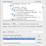
getInstanceCommand returns the command of the execution. It takes session ID, node name (which can be found by calling getSessionStatus), and instance number (which can also be found by calling getSessionStatus). The query URL looks like this:
http://cerebro-rsn2.loni.usc.edu:8021/getInstanceCommand?sessionID=cerebro-rsn2.loni.usc.edu:8020-453da129-c81b-4473-9fc0-8fe03481e492&nodeName=BET_0&instanceNumber=0
getOutputFiles returns the path of output files generated by the node. It takes session ID, node name, instance number, and parameter ID. The query URL looks like this:
http://cerebro-rsn2.loni.usc.edu:8021/getOutputFiles?sessionID=cerebro-rsn2.loni.usc.edu:8020-453da129-c81b-4473-9fc0-8fe03481e492&nodeName=BET_0&instanceNumber=0¶meterID=BET.OutputFile_0
3.2.5.6 Automatically clean up old files
If Automatically clean up old files in temporary directory is checked, then any session in the temporary directory that are older than two times the days to persist status will be removed. This will not happen under normal circumstances, because persistence database keeps track of all sessions, and no temporary directories older than days to persist status should exist. It happens in rare situations such as when the Pipeline server restarts with its persistence database manually deleted, or the temporary directory was used by other programs, and so on.
This specifies the maximum number of metadata generator threads used in workflows with Study module.
3.2.5.8 Warn when free disk space is low
If enabled, Pipeline will warn when temp and home directories’ free space goes below the specified %.
3.2.5.9 Server status
The server status refresh interval specifies how often should the server checks for grid usage counts and sends the information to the clients. The connected clients will get the server status information.
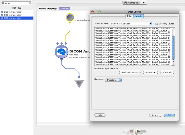
3.2.5.10 Directory source recursive timeout
This specifies the maximum time allowed in seconds of the recursive directory source listing feature. When user specifies a directory that contains lots of sub directories and files, the recursive directory source listing may take a long time. This timeout value limits the time allowed for a recursive listing on a directory.
3.2.5.11 External network access queue
This specifies the queue that has external network access enabled on its compute nodes. Some module may require external network access, and the general queue for the Pipeline server may not have that. By setting up a special queue that has external network access, user can submit modules with external network access checked on their Pipeline client, and the server will submit the jobs on that queue.
3.2.5.12 Validation warning
When there’s a missing input file or executable path in a workflow, and user tries to submit the workflow, Pipeline gives a validation error and asks the user to correct the invalid file. But in some circumstances the file may not exist yet at validation time, and will be valid at a later time, and as a result the workflow can’t be used as is. Validation warning solves this issue. If enabled, such invalid path will result in a warning message and user can proceed to submitting the workflow by dismissing the warning.
3.2.5.13 NFS directories for validation
If Pipeline server is used in grid environment, a shared file system such as NFS is often used. If user specified a valid file under non-NFS directory, it would pass validation but likely cause problem as the file is not accessible on each compute nodes. This issue can be solved by specifying all NFS directories of the system. Validation will catch files that are not under these specified directories.
3.2.5.14 Check and verify output files
If this option is enabled, Pipeline server will check the existence of output files after the module completed successfully. If output file was missing while the executable exited normally (return value 0), Pipeline will report the module as error/failed and not continue to the subsequent modules.
3.2.5.15 Test server library
By pressing the button, it will generate the instructions for testing the server library workflows. It uses command line interface to batch validate workflows, so you know if there’re any issues with your server library workflows.